DIY Electronics
Simple electronics as a hobby
6502 8-bit computer
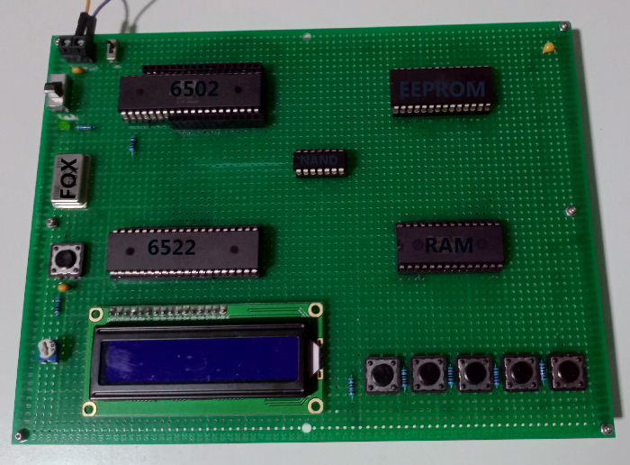
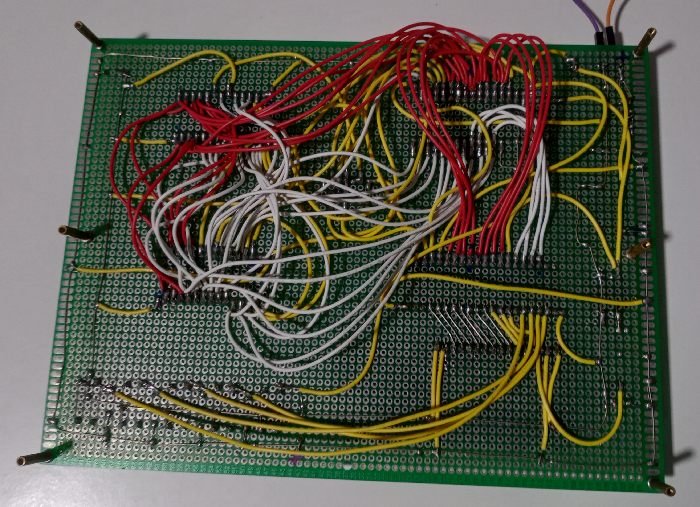
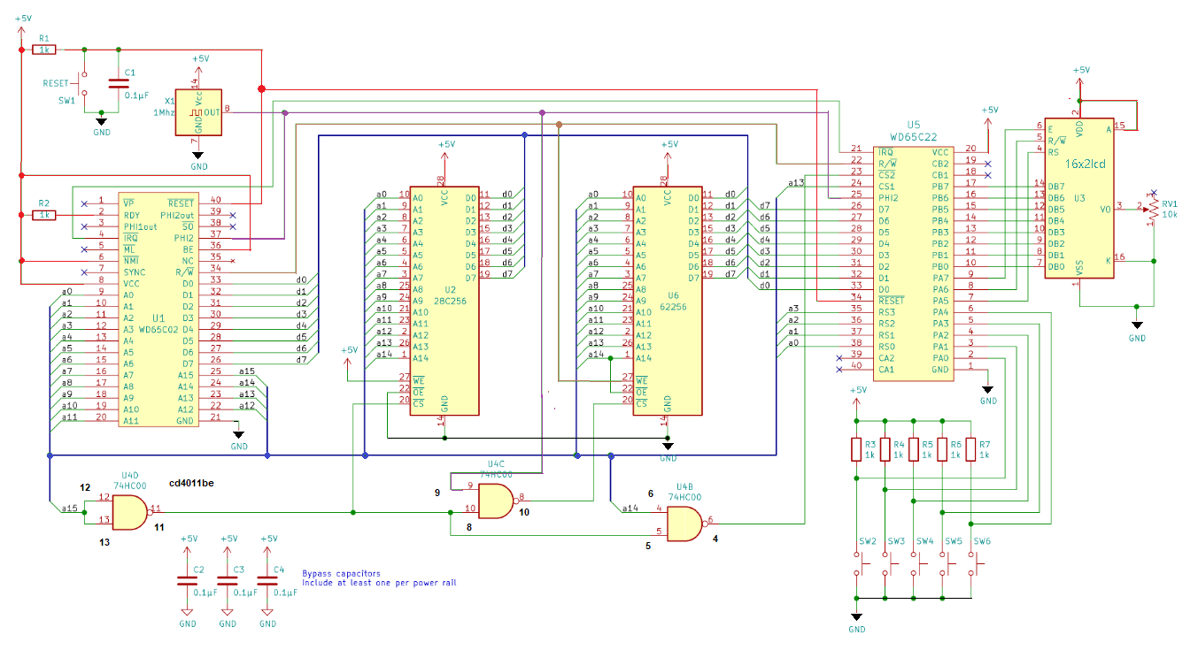 This is the basic schematic diagram of the 6502 computer with 8 data lines to the LCD 16x2 and the cd4011be NAND gate (black pin numbers) I used instead of the 74HC00 NAND gate (red pin numbers).
I bought the 6502 and other components from Ebay. Some components didn't work, so I turned to Mouser (more expensive, but better quality).
The main components are: 65c02 microprocessor (W65C02S6TPG-14), 65c22 I/O controller (W65C22S6TPG-14), AT28C256-15PU Microchip EEPROM, AS6C62256-55PCN Alliance Memory SRAM, cd4011be NAND gate, Fox 1MHz oscillator and HD44780U LCD 16x2 (no I2C). Except for the Fox oscillator NAND gate and LCD display all are bought from Mouser.
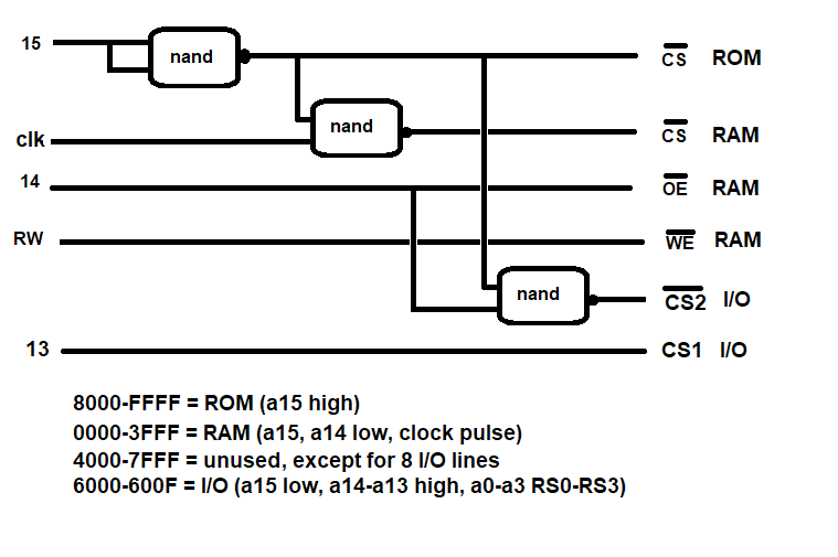 This schematic explains the different address lines in combination with the NAND gate to communicate with the EEPROM, RAM and I/O chip.
 The following code is compiled with Volker Barthelmann's vasm assembler website on a linux machine.
Next step is to copy the a.out to an sd-card, rename it to asm.bin and upload it to the EEPROM ( see project below). It's an easy and well-known game "guess the secret number" and needs 5 buttons. The first button is connected to pin 4 of the 6502 (IRQ) and with no connection to pin 21 of the 6522. When pressed the interrupt routine will run so fast that multiple overflows of a counter variable occurs and this will simulate a random number between 0 and 255.
To test parts of assembly code for the 6502 I use the assembler and emulator from mass werk (see below).
>>> Code for guessing game<<<
The next game uses the custom characters feature from the lcd. There is a video of Ben Eater explaining the use of interrupts in combination with the versatile interface adapter.
>>> Code for obstacle race game<<<
This board has the same components as the one above, but two zif sockets make swapping much easier, the LCD can easily be replaced and it is wired with 4 instead of 8 data lines. All pins of peripheral data port A of the 65c22 are available for buttons.
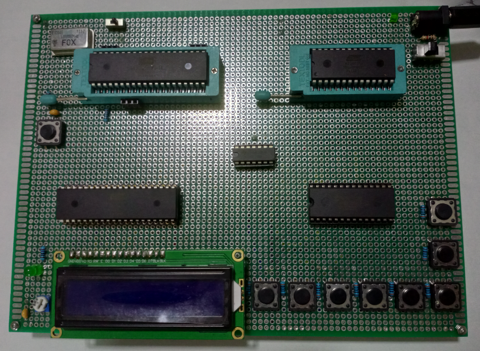
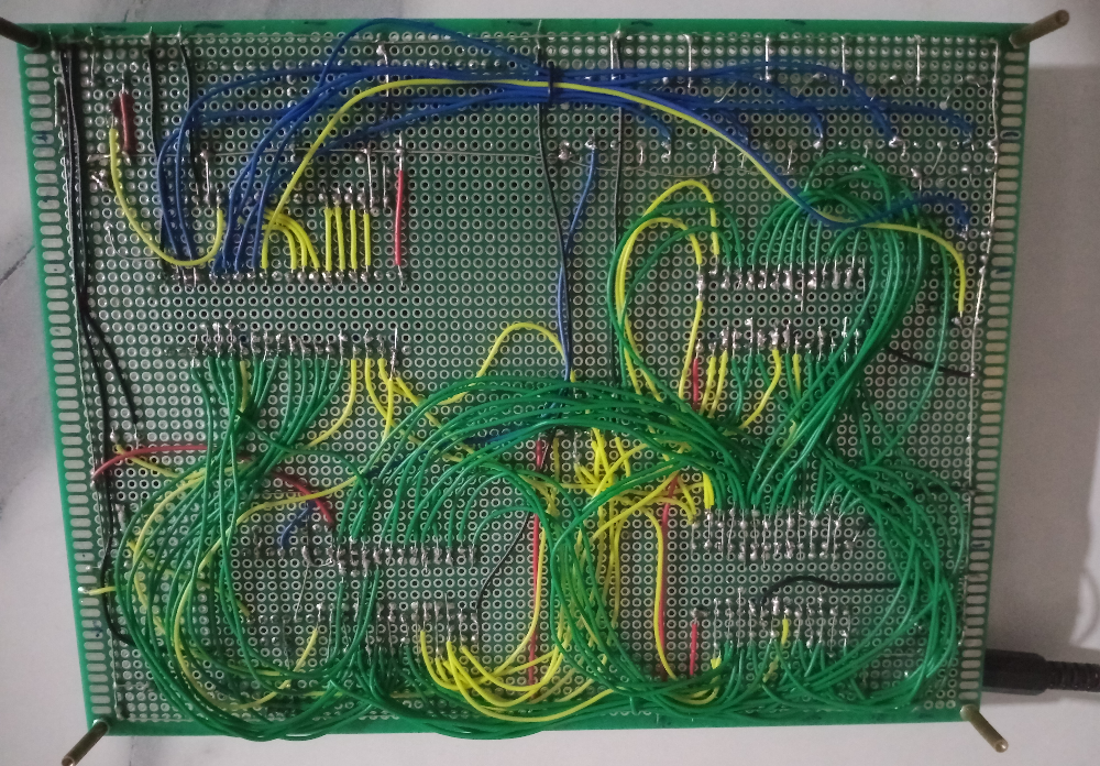
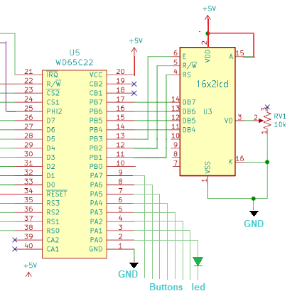 Here is an example of a simple message display with 4 data lines.
>>> Code for 2 messages with delay<<<
The next asm file is a hex, dec, binary converter, input one numeral, output the other two. It uses 6 buttons, up, down, left, right, enter and clear. At one point I had a problem with the EEPROM not storing the code correctly (just added a missing rts op-code). A way to solve this problem was to write all zeroes to the EEPROM and then it stored the changed code correctly. In this example I use sub-routines to convert first from string input to value and then from value to string output.Actually the index numbers are used instead of the input characters; for instance an A would have index 10 and a '0' would have index 0.
>>> Code for hex dec and binary converter (4-bit lcd) <<<
AT28C256 EEPROM programmer with sd_card
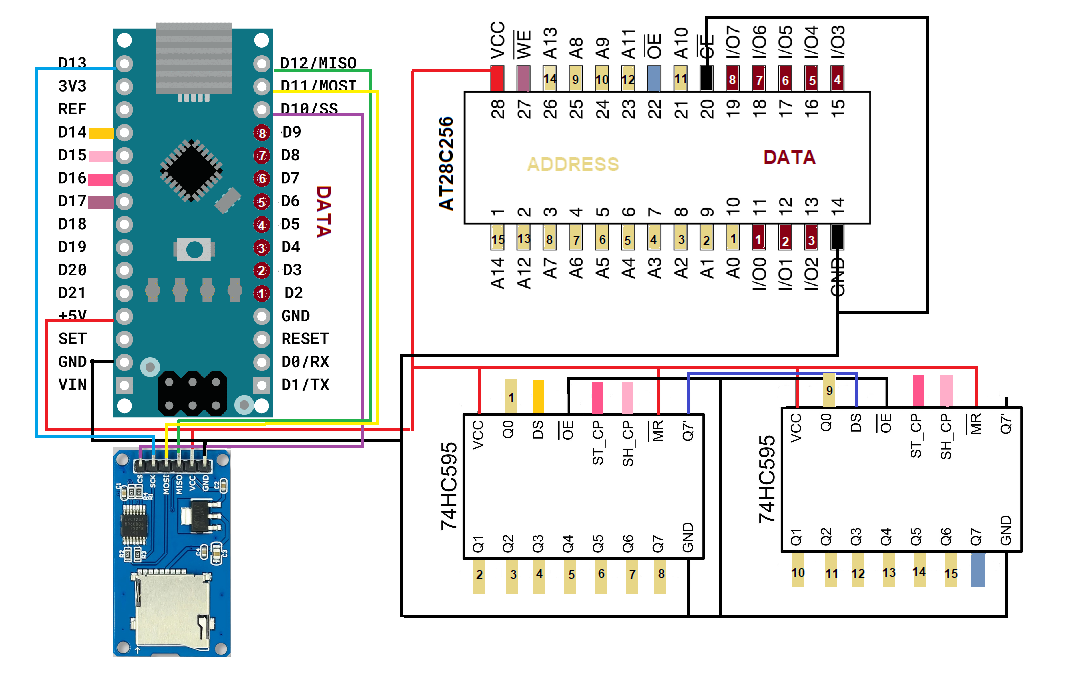 The 15 address pins of the AT28C256 eeprom are connected to the 16 output pins of the two shift registers. The last pin Q7 of the second shift register controls the OE (output enable) pin, being active low. By sending 16 bits as address the highest (msb) bit determines reading or writing together with the WE (write enable) pin (see code (address >> 8) | (outputEnable ? 0x00 : 0x80)).
To read data from the EEPROM CE and OE must be low and WE high.
To write data to the EEPROM CE and WE must be low (active) and OE high.
To get the sd card working with the Arduino NANO the sdfat library is used. The standard sd library from Arduino doesn't work properly.
To speed the program up I added a few lines so only the first and last 1000 bytes are written.
To read the eeprom remove the sd card, no writing will occure only reading.
AS6C62256 RAM read and write using Arduino MEGA
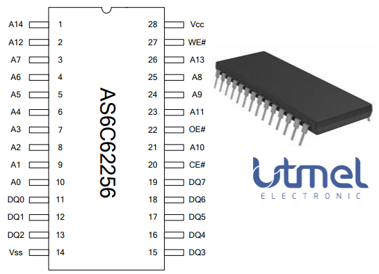 Not sure if the memory modules bought from various sources were okay, I wrote a small program to test read & write to RAM. PORTC (PC7) of the Mega is broken, so I used PORTD (PD7) instead.
6502 assembly language tips
To practise 6502 assembly I use the online emulator from mass:werk website and assembler. Open the assembler page using the link on the emulator page. After the code is assembled successfully you can transfer the binary to the emulator and run it from there. For compiler directives, labels and such go to website .
Some tips:
An instruction using zero page addressing mode has only an 8 bit address operand. This limits it to addressing only the first 256 bytes of memory (e.g. $0000 to $00FF) where the most significant byte of the address is always zero. In zero page mode only the least significant byte of the address is held in the instruction making it shorter by one byte (important for space saving) and one less memory fetch during execution (important for speed).
The second page consists of memory addresses 0100 to 01FF and is the location of the 6502's stack.
You can only set this 8-bit stack pointer via the X register; you must place the value in the X register and transfer it to the stack pointer with the TXS (transfer X register to stack pointer) op code. Because the stack grows downward, it is good practice to initialize the stack pointer at the beginning of any 6502 program with the following code:
LDX #$FF ;set pointer to very top of stack
TXS
The 6502 clears the carry bit to indicate a borrow, but you have to set it first:
SEC ; carry set
SBC #ff ;subtract 255
BCC BORROW ;a borrow occurred
Comparison is a subtraction; comparing 5 to 6 would be a matter of subtracting 6 from 5 and setting the appropriate status flags. In this situation (5 minus 6) a borrow would occurs, indicated by a clear carry. Therefore, after a compare operation, a clear carry indicates less than, and a set carry indicates greater than or equal to.
Flags
The carry flag is only affected by arithmetic (ADC, SBC, and CMP,CPX,CPY compares) and shift operations (ASL, LSR, ROL, and ROR), except when explicitly changed (with CLC, SEC, or PLP).
Flags set or cleared with most operations are the Negative and Zero flags. The Negative flag reflects the state of the eighth (most significant) bit of the result of the operation, and the Zero flag is set whenever the result is equal to 0 (all bits cleared). All operations that work with a value set these flags, including the load (LDA, LDX, and LDY) and transfer (TAX, TAY, TSX, TXA, TXS, and TYA) op codes.
BIT op code
When used it will do a AND operation between memory and accumulator and place the eighth bit in the Negative flag and the seventh bit in the Overflow flag without affecting the contents of any register.
SED (set decimal mode)
In this mode only ADC and SBC are effected. The 4-bit nibbles are treated as decimals. This means that $1C (1 + 12) plus $1E (1 + 14) equals $30 (1+1(+c), 12+14(-10 overflow)= 16 => 0). Another example: $1a plus $10 also equals $30 (1+1(+c), 10+0(-10 overflow) = 0). One more: #$1f plus #$1f equals $34 (1+1(+c), 15+15(-10 overflow) = 20 => 4, remember that 16=>0, 17=>1,18=>2,19=>3,20=>4).