DIY Electronics
Simple electronics as a hobby
Scare the neighbours' cat
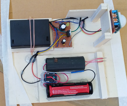
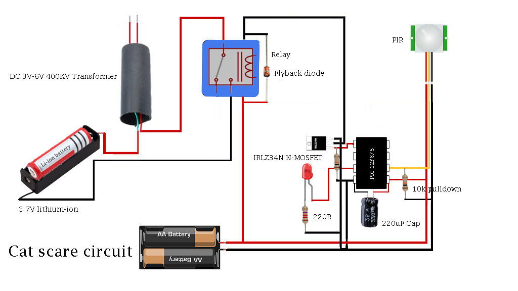
A PIR sensor picks up any movement and triggers the relay. The DC boost step-up transformer of 400k (more like 10K) volt
gives a short spark. The view and sound is strong enough to scare a cat. The flyback diode was not enough to stop the
microcontroller from resetting after each burst, so I put a 220uF capacitor between Vcc and Gnd pins of the IC. That helped.
Another thing is that it takes more than 2 minutes for the PIR to settle before operating properly and about 30 seconds after
a detection.
>>> PIC12F675 code <<<
Police LED strobe lights
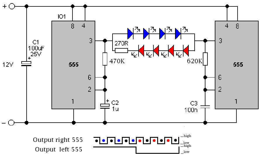
The given police light circuit consists of two 555 astable multivibrators. Pins 3 output a square wave of high and low voltage; one with a lower oscillation frequency and the other with a higher frequency. The circuit diagram shows why blue and red LEDs blink 3 times alternately. The decoupling capacitor of 100uF is ESSENTIAL. It will reduce the significant negative voltage spikes in the circuit.
Traffic lights using two 555 timers
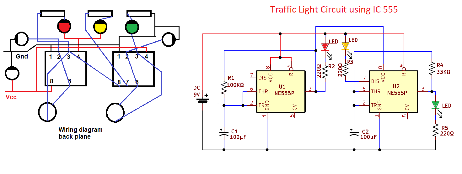
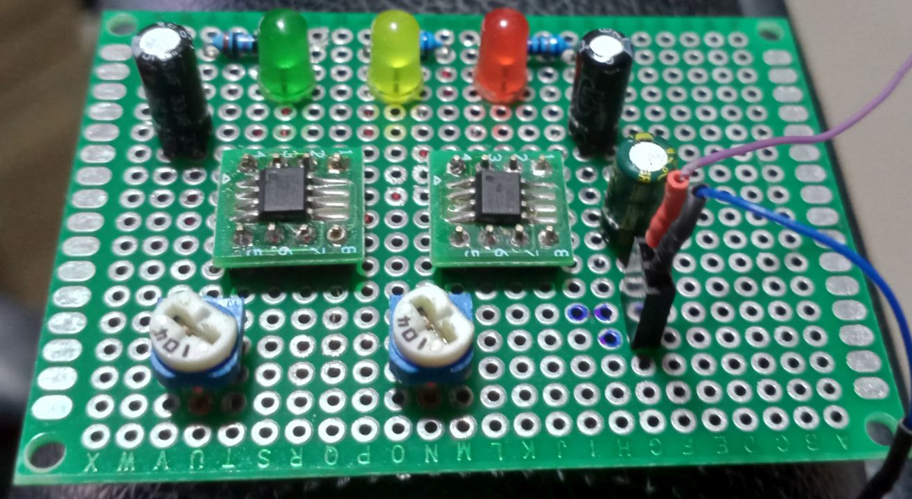
The red LED has an equal on-off period and when it is off, the first 555 delivers power to the second 555. This illuminates the Green LED and then the second 555 changes state to turn off the Green LED and turn on the Orange LED for a short period of time before the first 555 changes state to turn off the second 555 and turn on the red LED. A supply voltage of 9v to 12v is needed because the second 555 receives a supply of about 2v less than rail. This circuit also shows how to connect LEDs high and low to a 555 and also turn off the 555 by controlling the supply to pin 8. Connecting the LEDs high and low to pin 3 will not work and since pin 7 is in phase with pin 3, it can be used to advantage in this design.
Distance measurement with temperature correction
Measure distance using an ultrasonic sensor, a temperature/humidty sensor connected to an ATmega328p mircocontroller ( or Arduino uno) and a 16x2 LCD display. Temperature has a substantial impact on ultrasonic distance measurement; using this formula to compensate for temp. and humidity. speed of sound = 331.4 + (0.606 * temp) + (0.0124 * humidity)
>>> Arduino code <<<
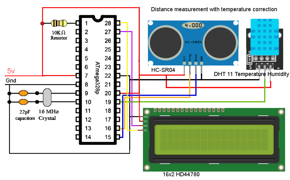
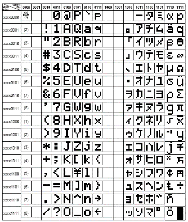
16x2 LCD display
Using switches and push buttons to send instructions and data to this 16x2 LCD.
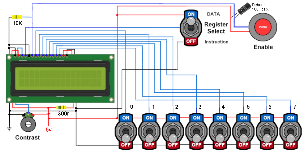
16x2 commands
No.	Instruction	Hex	Binary
1	Function Set: 8-bit, 1 Line, 5x7 Dots	0x30	0011 0000
2	Function Set: 8-bit, 2 Line, 5x7 Dots	0x38	0011 1000
3	Function Set: 4-bit, 1 Line, 5x7 Dots	0x20	0010 0000
4	Function Set: 4-bit, 2 Line, 5x7 Dots	0x28	0010 1000
5	Entry Mode	0x06	0000 0110
6	Display off Cursor off
(clearing display without clearing DDRAM content)	0x08	0000 1000
7	Display on Cursor on	0x0E	0000 1110
8	Display on Cursor off	0x0C	0000 1100
9	Display on Cursor blinking	0x0F	0000 1111
10	Shift entire display left	0x18	0001 1000
11	Shift entire display right	0x1C	0001 1100
12	Move cursor left by one character	0x10	0001 0000
13	Move cursor right by one character	0x14	0001 0100
14	Clear Display (also clear DDRAM content)	0x01	0000 0001
15	Set DDRAM address or coursor position on display	0x80 + address*	1000 0000 + address*
16	Set CGRAM address or set pointer to CGRAM location	0x40 + address**	0100 0000 + address**


Init
0011 1000   //  2-line, 8-bit, 5x7 dots
0000 1111     //Display on, Curson blinking command.
0000 0001     //Clear LCD
0000 0110     //Entry mode, auto increment with no shift.


0000 0010     // HOME
Cursor position    // 1000 0000  to 1000 1111 are visible on first line and
 1100 000  to 1100 1111 is visible on second line.
Custom character // 0100 0000 (0x40) access to cgram (0x40 | (location << 3)
 8 character (0-7) , followed by 8 bytes (rows) of 5 bits (columns) as data to define the character.
