DIY Electronics
Simple electronics as a hobby
IC training board
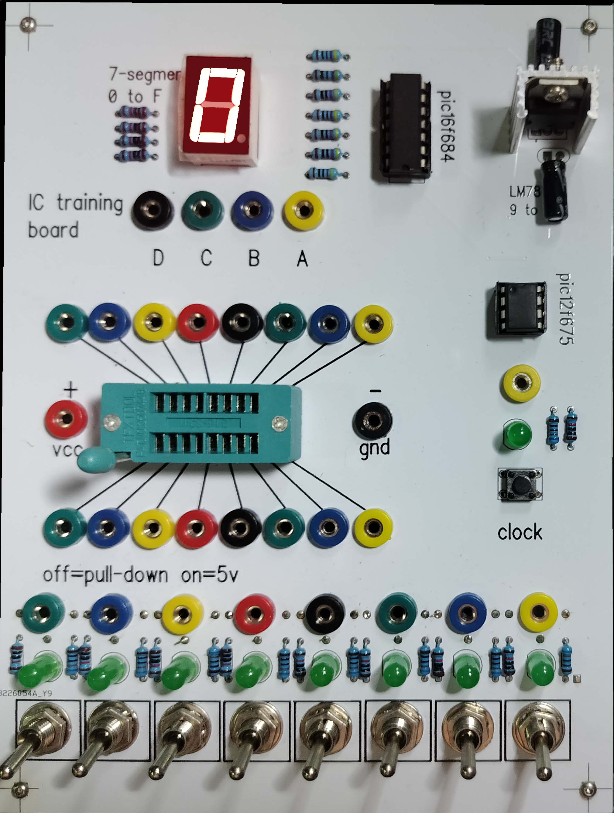 This IC training board is made for a pupil who liked electronics.
Top right shows a LM7805 regulator to bring down the voltage of a 9 volt battery to 5 volt.
A Pic16F684 is used to convert (4-bit) inputs A B C and D to a number on the 7-segment display (0-F).
The 4 resistors on the top left are pull-down resistors for the inputs.
This IC training board is made for a pupil who liked electronics.
Top right shows a LM7805 regulator to bring down the voltage of a 9 volt battery to 5 volt.
A Pic16F684 is used to convert (4-bit) inputs A B C and D to a number on the 7-segment display (0-F).
The 4 resistors on the top left are pull-down resistors for the inputs.
On the right is a PIC12F675 that outputs a single pulse to the yellow (2mm banana) socket and green LED when the button is pushed.
Pushing and holding the button for a few seconds will start an automatic sequence of pulses with 1 second delay.
One more push stops the loop. One resistor is for the LED ,the other one is to pull-down the button input.
In the middle there is a Zero Insertion Force (ZIF) socket to insert different IC's. The plus (vcc) and minus (gnd) sockets are
connected to respectively 5 volt and ground of the LM7805 output.
The toggle switches at the bottom are either connecting the sockets to 5 volt or ground and
again one resistor for the LED and one pull-down resistor.
 By inserting a logic gate IC, e.g. cd4081 AND-gate, and connecting the sockets with wires, you can test the output on the 7-segm. display.
A 4-bit counter IC, like cd4520 and a running clock pulse will update the 7-segm. display every second.
By inserting a logic gate IC, e.g. cd4081 AND-gate, and connecting the sockets with wires, you can test the output on the 7-segm. display.
A 4-bit counter IC, like cd4520 and a running clock pulse will update the 7-segm. display every second.
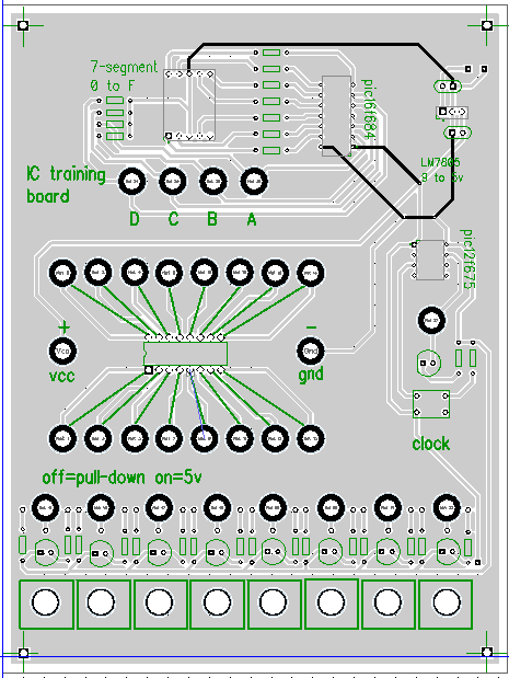
<- Picture of the PCB-layout.
Gerber files are called zif_board_2mm_v2_gerber.zip.
Game based on shift register IC
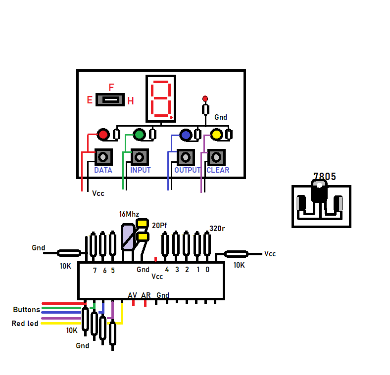
The picture shows the user interface with 7-segment display, toggle switch, 4 buttons and LEDs.
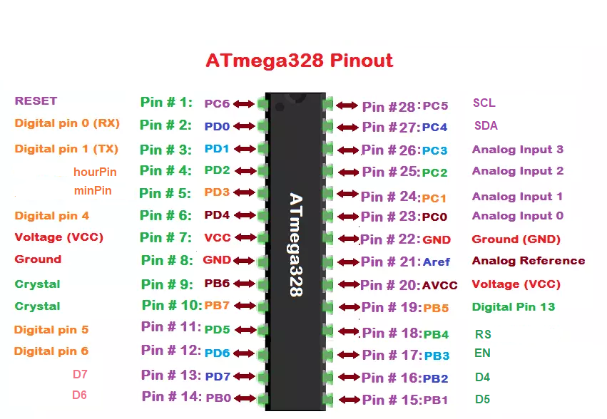
At the bottom half you see an Atmega 328p with pinouts.
Pins 0 to 7 are connected to the 7-segment display with current limiting resistors of 320 Ohm.
Pin 8 is used as input to switch between Easy and Hard. Pins 9 to 12 are inputs for the buttons.
Pin 13 is output for the red LED.
A voltage regulator 7805 is used to reduce the 9 volts of the battery to 5 volts.
The way this game works is shown in a YouTube video Game shift register
Working of the shift register
The 74HC595 has two 8-bit registers. The first is referred to as the Shift Register, and the second as the Storage/Latch Register.Every time the 74HC595 receives a clock pulse, two things happen:
The bits contained in the shift register are shifted to the left by one position. Bit 0’s value is pushed into bit 1, while bit 1’s value is pushed into bit 2, and so on.
Bit 0 in the shift register accepts the current value on the DATA pin. On the rising edge of the clock pulse, if the DATA pin is high, 1 is pushed into the shift register, otherwise 0.
This process will continue as long as 74HC595 is clocked.
When the latch pin is enabled, the contents of the shift register are copied to the storage/latch register. Each bit of the storage register is linked to one of the IC’s output pins QA-QH. As a result, whenever the value in the storage register changes, the output changes.
>>> Arduino code <<<
Dec Hex Binary game
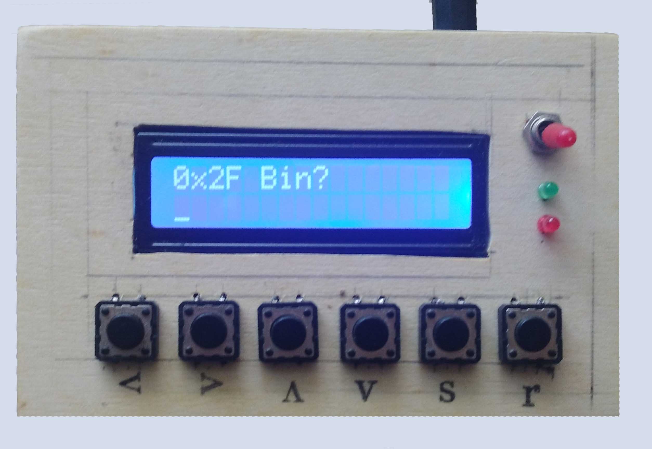
The game is to convert decimal, hex or binary numbers to another number system. With the push buttons you can move
the cursor, increase or decrease the digits, Show if the conversion has been done correctly and Restart the game.
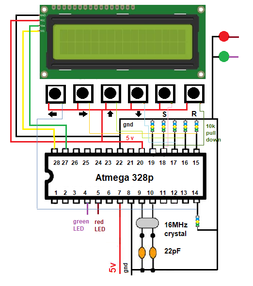
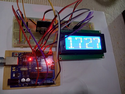
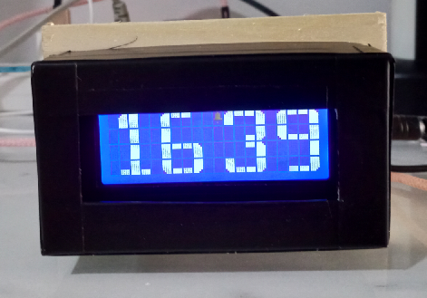
Arduino clock using rtc 3231 and 20x4 lcd 4x4 font display
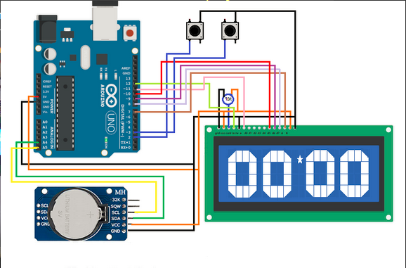
The clock displays only hours and minutes.Two buttons to control hours and minutes.
Changing the minutes will set the seconds to zero.
 >>> Arduino code <<<