DIY Electronics
Simple electronics as a hobby
Full adder based on NOR gates
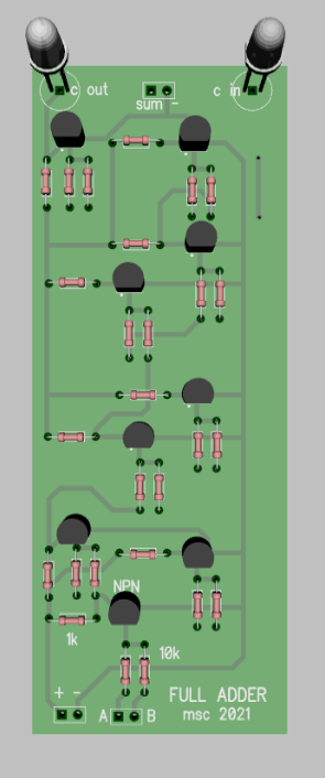
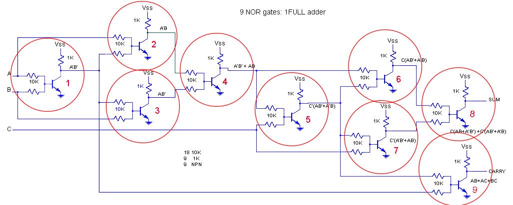
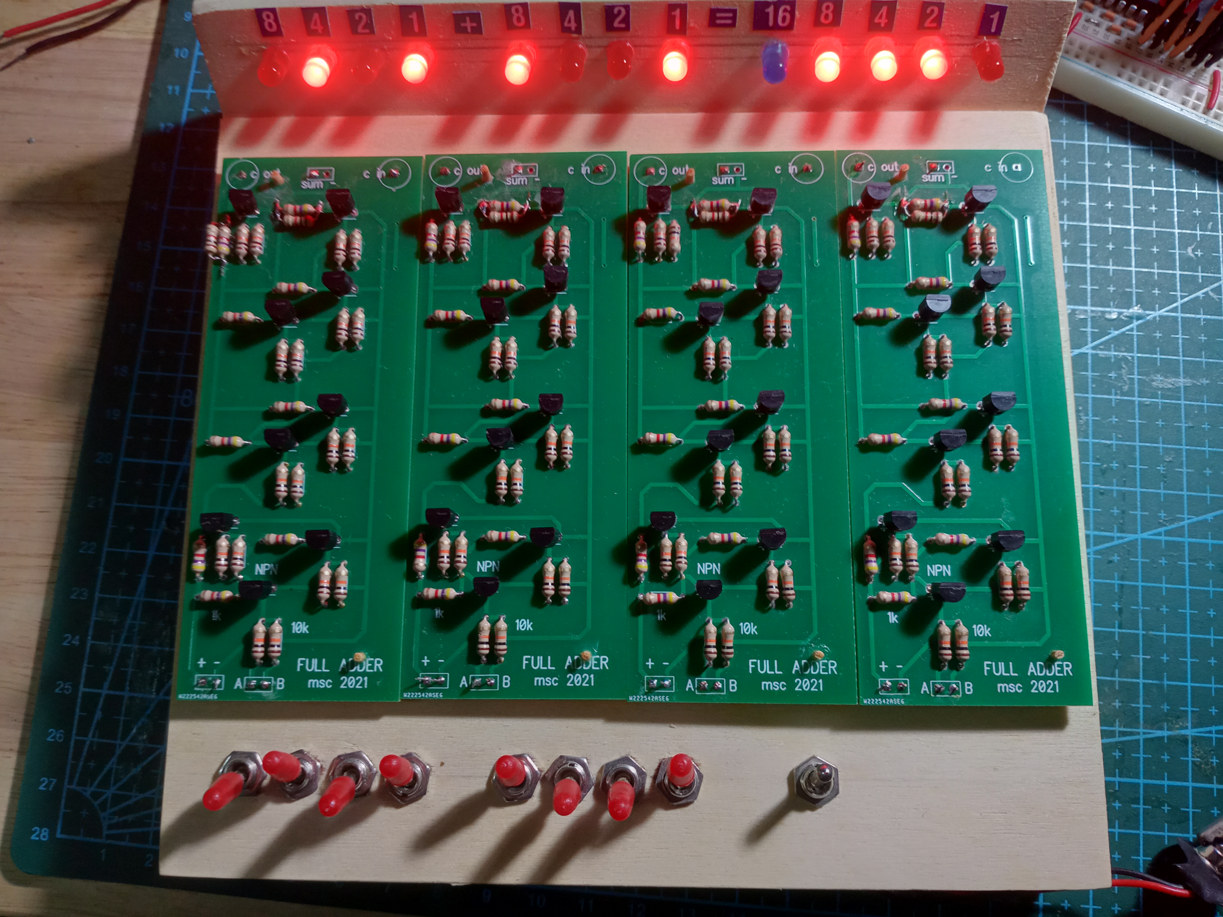 With only transistors and resistors 9 NOR gates are built for 1 full adder. Four full adders construct a 4-bit adder.
PIC16f690 and 16x2 LCD library
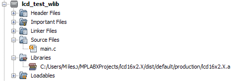
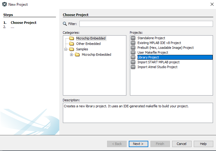 Step 1: Choose library project
Step 2: Create header and source file(s).
Step 3. Build and the library "name.X.a" is created.
Step 4. In a new project add the library to the libraries folder.
Step 5. Add #include "../name.X/header.h" to your main.c
Step 6: Build

 >>> code of lcd16x2.c and lcd16x2.h <<<
Voltmeter pic12f675 i2c
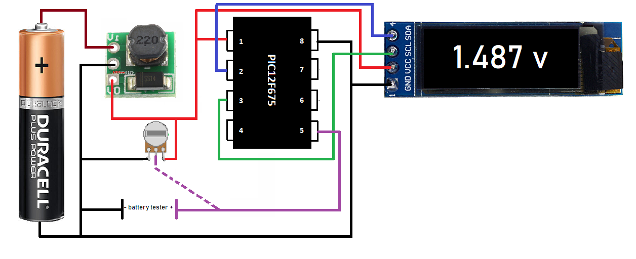
 This voltmeter is build with a pic microcontroller with I2C code to control the OLED. A boost converter is
use to power the circuit. Only batteries less than 5 volt can be measured. The code uses ADC to determine the voltage.
This voltmeter is build with a pic microcontroller with I2C code to control the OLED. A boost converter is
use to power the circuit. Only batteries less than 5 volt can be measured. The code uses ADC to determine the voltage.
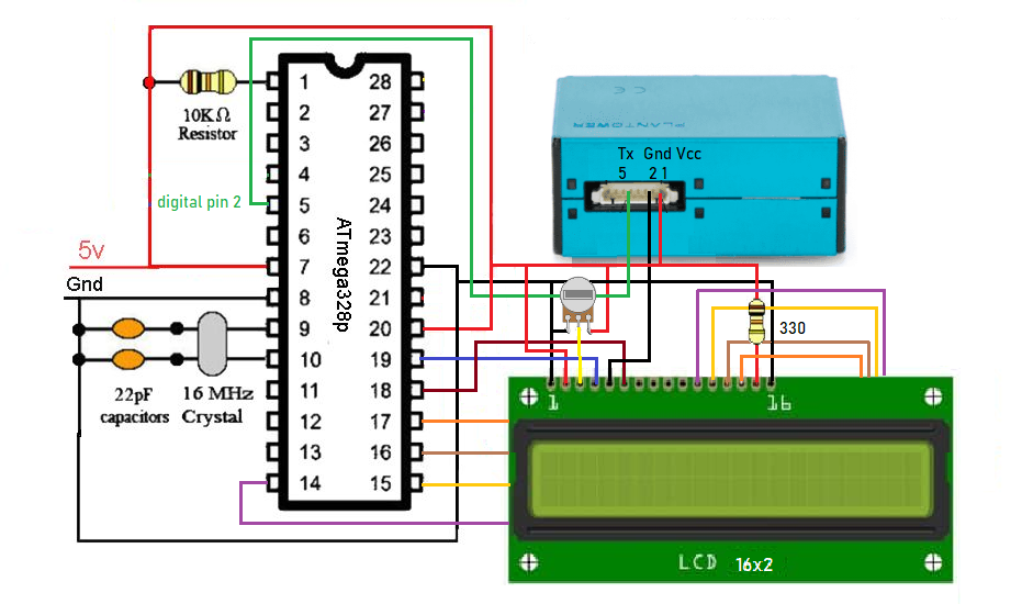
pms5003 sensor circuit
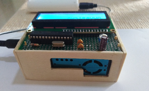
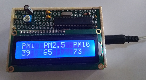 The importance here is to use your own datastructure and let the sensor run its serial data without
interruption. It can't handle delays. The capacitor in the circuit is just for decoupling.
The importance here is to use your own datastructure and let the sensor run its serial data without
interruption. It can't handle delays. The capacitor in the circuit is just for decoupling.
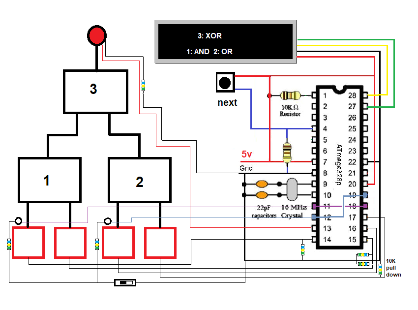
Logic gates game
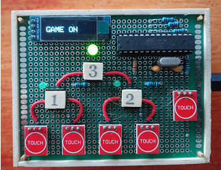 Touch the TTP223 button on the left to start the game. Figure out which logic gates are used in position 1,2 and 3 by touching the 4 buttons and see how the LED above logic gate 3 respond. The 4 gates that are being used are AND, OR, XOR and NAND. There is only 1 of each gate per game. When you think you know which gate goes where, touch the left button again to see the correct configuration on the display.
 >>> Arduino code <<<