DIY Electronics
Simple electronics as a hobby
Clap switch
A lot of clap switch circuits on the Internet are not very sensitive to say the
least.
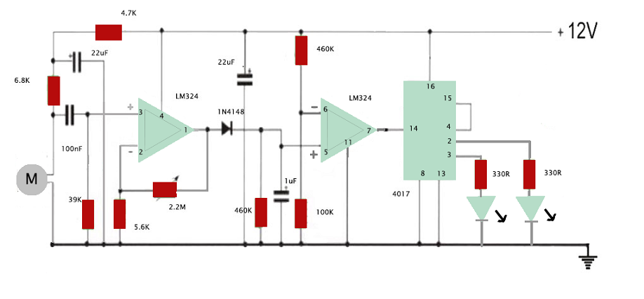
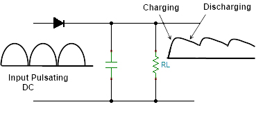
This circuit is different. It even picks up background sounds from the TV. It needs no less than 12
volt to work properly.
Sound is picked up by a electret condensor mic and sends out an audio signal.
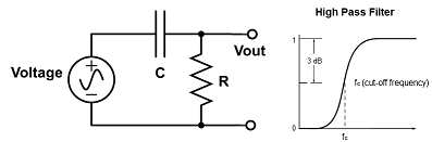
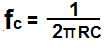
The input to the first op-amp is filtered for high frequency signals (high pass filter)
and rejects low frequency signals. The cutoff frequency is 41 Hertz.
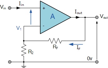
The filtered input voltage signal is applied to the non-inverting (+)
input terminal. The result of this is that the output signal is "in-phase" with
the input signal.
Feedback control is achieved by applying a small part of the
output voltage signal back to the inverting (-) input terminal via a Rf - R2 voltage divider network, in our case the
2.2M potentiometer (I replaced it by a 1.5M resitor) and 5.6K resistor. The gain is 1+1500/5.6 = 269.
The second op-amp operates as an comparator and if the voltage of (+) is higher than (-), being 460/560 * 12 = 9.8 volt the output turns high, otherwise it turns low.
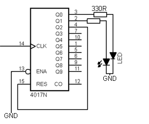 This signal is connected to the pin 14, the clock of a decade counter 4017 ic. Pin
3 is turned on when IC is powered up. The first clock signal turns on pin 2 and turns
off pin 3. Finally pin 4 is turned on.
Because pin 4 is connected to pin 15, this resets the IC and turns on pin 3. Pin 13
is the clock enable pin and active low, so it should be kept low.
This signal is connected to the pin 14, the clock of a decade counter 4017 ic. Pin
3 is turned on when IC is powered up. The first clock signal turns on pin 2 and turns
off pin 3. Finally pin 4 is turned on.
Because pin 4 is connected to pin 15, this resets the IC and turns on pin 3. Pin 13
is the clock enable pin and active low, so it should be kept low.
Build your own 555 timer with transistors
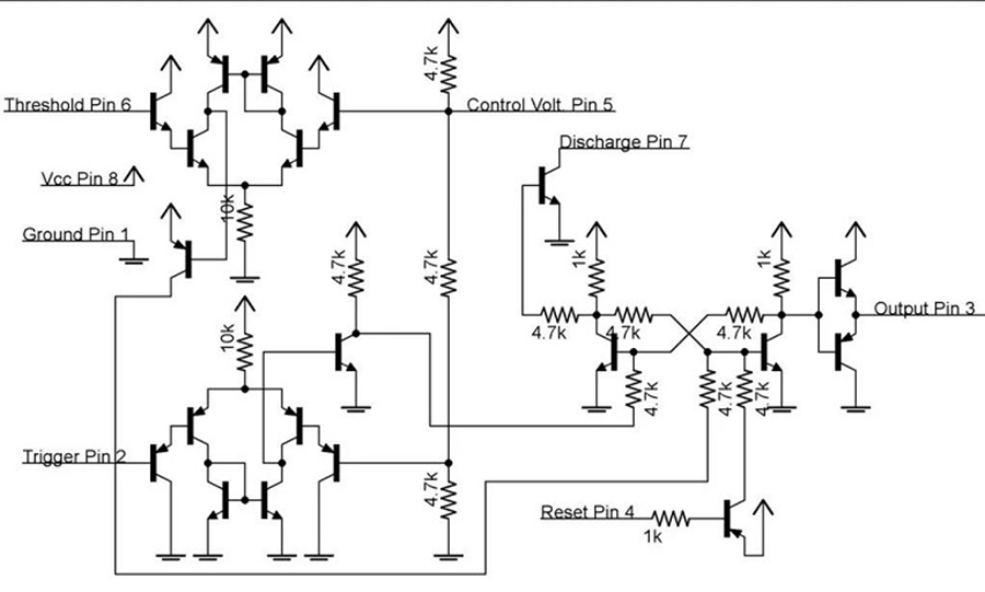
This diagram and the instructions to build your own 555 timer come from instructables website. The diagram is not exactly the same as the bipolar version of the original chip, but it comes close with two comparators, a S-R latch, a simple discharge, reset and output circuit.
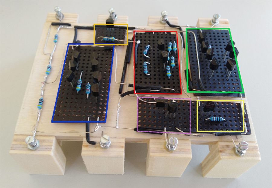
In the middle we see the S-R latch (red), on the left (blue) and right side (green) we have the two comparators. Two transistors service the output (purple), one transistor and resistor for the reset (yellow) and the same for the discharge (orange).
Build a 555 timer with an op-amp and NOR logic gates
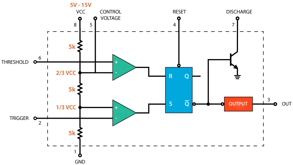 The block diagram shows a representation of the internal circuitry of the 555 timer. There are three 5kΩ resistors connected
together to form a voltage divider between vcc, pin8 and ground, pin 1. Pin 6 is connected to the non-inverting input and pin 2 to the inverting input of two comparators. The outputs of the comparators reset or set the SR-latch. Q-bar drives the output of pin 3, either sink or source and it is also switches pin 7 to ground on and off. Pin 4 when turned LOW resets the SR-latch.
The block diagram shows a representation of the internal circuitry of the 555 timer. There are three 5kΩ resistors connected
together to form a voltage divider between vcc, pin8 and ground, pin 1. Pin 6 is connected to the non-inverting input and pin 2 to the inverting input of two comparators. The outputs of the comparators reset or set the SR-latch. Q-bar drives the output of pin 3, either sink or source and it is also switches pin 7 to ground on and off. Pin 4 when turned LOW resets the SR-latch.
 SR-latch using NOR gates.
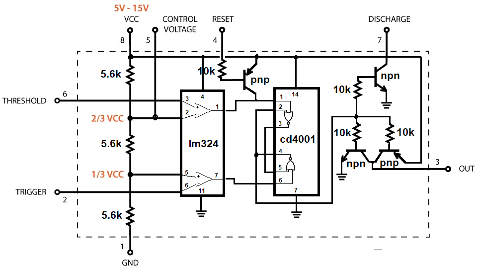 In this circuit an op-amp LM324 is used to provide the two comparators. The outputs of the comparators go to two NOR-gates of
a quad NOR-gate IC, cd4001be. The outputs of the NOR-gates are feed back to one of the inputs of the other gate, creating a SR-latch. One of the outputs drives the transistors for pin 3 and pin 7.
In this circuit an op-amp LM324 is used to provide the two comparators. The outputs of the comparators go to two NOR-gates of
a quad NOR-gate IC, cd4001be. The outputs of the NOR-gates are feed back to one of the inputs of the other gate, creating a SR-latch. One of the outputs drives the transistors for pin 3 and pin 7.
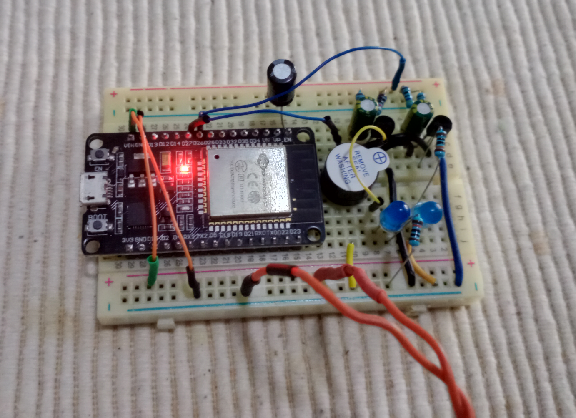
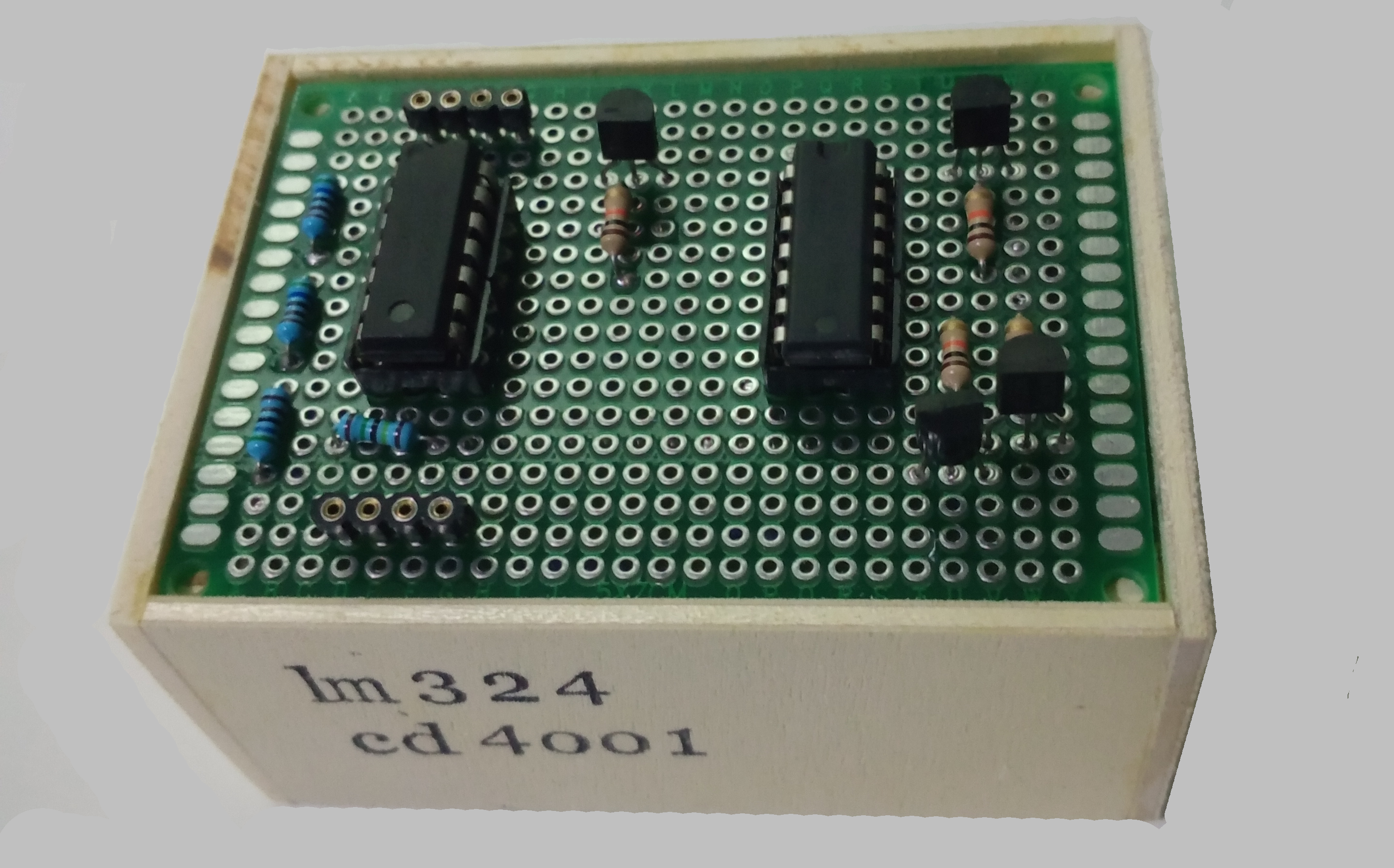 The circuit board.
ESP32 Web Server using WiFi AP or WiFi client
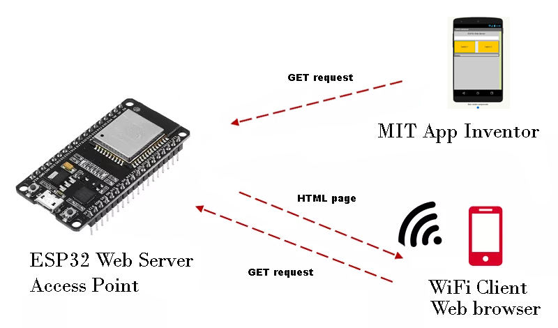
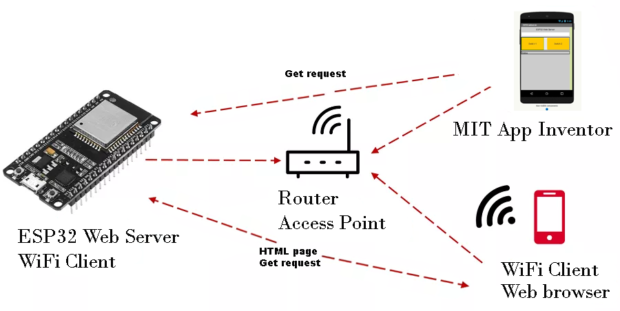 Left shows esp32 as Access Point, right show esp32 as WiFi client in an existing WiFi-network.
>>> Arduino code <<<
Esp32 wifi buzzer
 Accessible from the internet to activate buzzer using browser.
>>> Esp32 buzzer code <<<
Esp32 ntp client
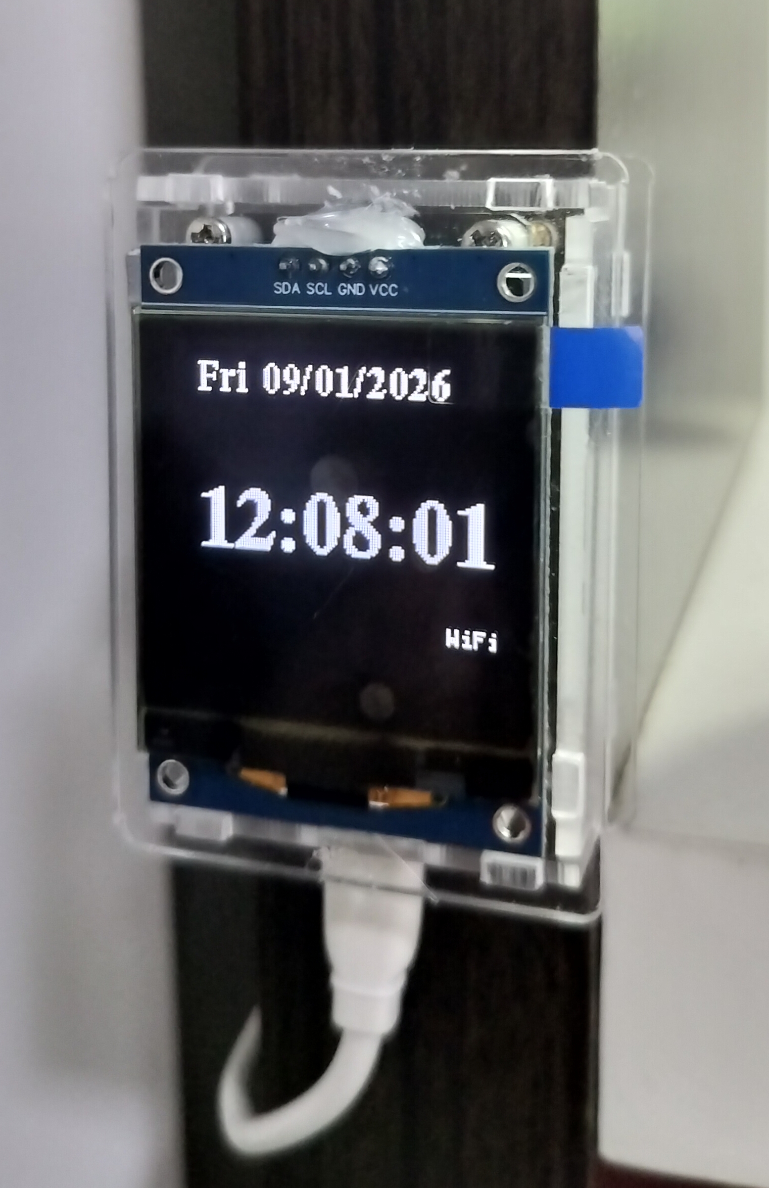 Once every 24 hours (tm_hour ==0) an internet connection is made with an NTP server to get current time, configTime() starts a background process to access NTP,it needs to be called only once in setup()
When calling getLocalTime(&timeinfo) it will return time every second. There is no need to use a delay() function. The u8g2 libary is used to display text on the 128x128 lcd.
I discovered that the function WiFi.mode(WIFI_STA) at the start of a new wifi connection is crucial for the right type of connection after it has been disconnected with WiFi.mode(WIFI_OFF).
I added a function called sntp_set_time_sync_notification_cb(cbSyncTime) to check if there was a successful ntp response. It's part of the build-in esp_sntp library. The function sntp_set_sync_interval(...) is set to 55 minutes. When it can't make a NTP connection it will terminate and try again 55 minutes later. >>> Esp32 ntp client code <<<
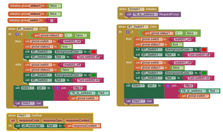
MIT App inventor
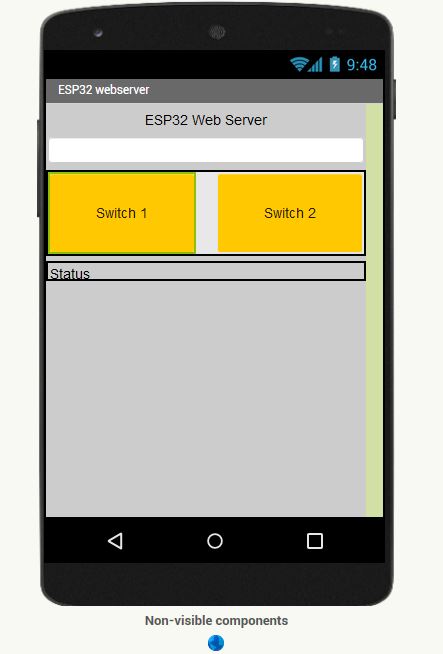
With MIT app inventor you can build your own Android phone apps.
Check out the MIT App Inventor website. You either connect to an existing Wifi network, like the esp32 and enter its local IP-address or you connect your phone to the esp32 Access Point and enter the password. The IP-Address of the AP is always 192.168.4.1
ESP32 web server with 4x4 keyboard
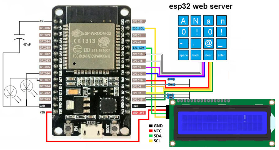
You enter SSID and password of your local wifi network or AP from your phone with the 4x4 keyboard
>>> Arduino IDE code <<<