DIY Electronics
Simple electronics as a hobby
Updated: 7 September 2025
Page 1 Page 2 Page 3 Page 4 Page 5 Page 6 Page 7 Page 8 Page 9 Page 10 Page 11 Page 12 Page 13 Page 14 Page 15
Documents
Datasheets
w65c02s - microprocessor from Western Design Centerw65c22s - versatile interface adapter
16x2 lcd - hitachi 16x2 lcd display
AT28C256 - 256-Kbit (32,768 x 8) Paged Parallel EEPROM
AS6C62256 - CMOS static random access memory
RNG90 microchip - RNG90 CryptoAuthentication
Pinouts
Overview - Atmega328, Arduino mega, Arduino uno, Attiny, Esp32Pic16f690, Pic16f684, Pic12f675, Pic10f200, 555 timer
74ls86, 74ls283, 74ls173, 74ls245, 74ls157
Projects
Random numbers
RNG90 microchip - Arduino code generates 256 bits of random numbers - sketchNIST test suite - Using the NIST test suite to show the likelyhood of randomness
Arduino Atmega328p
Arduino tachometer - 555 PWM - IR sensor - ATmega328p oled - sketchArduino "Simon says" - Arduino sketch
Distance measurement with temperature correction - Arduino code
Dec Hex Binary game - Arduino code for the hex game
RTC3231 clock - Arduino code
pms5003 sensor circuit - Arduino code
Logic gates game - Arduino code
Op Amp
Brushless motor with IR sensor - brushless motor with reed switchClap switch
Game based on shift register IC - Arduino code for the shift register game
555 timer
Build your own 555 timer with transistorsBuild a 555 timer with op-amp and NOR logic gates
Police LED strobe lights
Staircase lights using 555 timer
Monostable 555 with touch plate
ESP32
ESP32 Web Server using WiFi AP or WiFi client -Arduino sketch - MIT App inventorESP32 Web Server with 4x4 keyboard - Source sketch
esp32cam with PIR sensor - esp32cam write to sd-card
PIC microcontrollers
Scare the neighbours' cat - Source codeVoltmeter pic12f675 i2c - Pic12f675 code (XC8 compiler)
Create a lcd16x2 4-bit library for pic12f690 - code of lcd16x2.c and l cd16x2.h
PIC12F629 PWM in MPASM assembler - MPASM code
PIC12F629 dice in MPASM assembler - MPASM code
PIC12F629 button interrupt in MPASM assembler - MPASM code
PIC10F200 rolling die in MPASM assembler - MPASM code
Linear feedback shift register - PIC 16F684 code - LFSR code in C
Random flasher number generator - PIC 16F690 code
Seeeduino xiao
Animation using a Seeeduino xiao and Oled 128x64 - Source code - Convert BMP to HEX using c#Seeeduino Xiao - HID device to emulate keyboard - Source code - HID code
Arduino Attiny
Program ATtiny85 using Arduino UNOHappy birthday gadget using ATtiny85
Silhouette game with Arduino and Oled 128x64
Raspberry Pi
Raspberry Pi LCD 20x4 - RSS feed - lcd_display.service - aqi.sh - read_aqi.c - read_rss.cMIT app Inventor
Score Card using MIT App Inventor - Code in block modeMemory game for Android phone - Code in block mode
65c02
6502 8-bit computer - build and schematic diagramAT28C256 EEPROM programmer with sd_card - code for Arduino NANO
6502 assembly language - tips and tricks
6502 instruction reference - description of 6502 op-codes
ascii table - in hex and dec
Building an 8-bit breadboard computer
Building an 8-bit computer - instead of using broadboards the components are soldered on PCBs4-bit multiplier - hardware circuit to multiply two 4-bit numbers
Microbit
Micro:bit as slot-machine - Code for slot machine in JavascriptMiscellaneous
4 bit adder - full adder built with transistors and resistors16x2 LCD display - 16x2 commands
8 queens problem in Python
Explanation of 15 small electronic circuits - DC boost converter - Park assist - Astable multivibrator 555 timer - Heart rate sensor - JK flip flops - 1 bit full adder - Key code comparator - VU meter - Oscillator - DC boost converter with load - Clap switch - 7-segments counter - Quad oscillator - Tone burst generator - Ultrasonic distance measurement
Fibonacci numbers in C - using strings to add large numbers
Quick sort - code in C
Split string - code in C
Kaprekar's constant - code in C
Cryptography
Diffie-Hellman key exchange - Explanation of the Diffie-Hellman key exchangeRSA - Explanation of the RSA algorithm
Diana cipher wheel - Diana Cryptosystem replica
Arduino tachometer
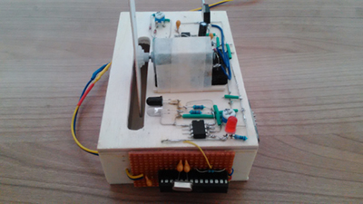
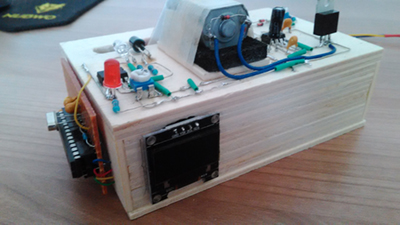
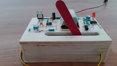
For this project I used a small DC motor. A sandpaper nail file is hot-glued to its shaft as a
makeshift propeller. There are three distinct circuits to this project. The first one is to control
the speed of the motor. A ne555 timer is used and PWM (pulse width modulation) for that purpose. PWM
works like a switch, turning the motor on and off very quickly.
 The second circuit is an IR sensor. Every time the propeller
passes the IR-LED and photodiode a signal is generated and the output goes high. The third
circuit comprises of an ATmega328p chip and an OLED 128x64 display. It takes the signal from the IR circuit as input and
calculates the rotation speed and shows the results on the display.
Click
here
to see the video.

NE555 Pulse Width Modulation
 This circuit controls the speed of the motor by turning the
potentiometer (P1). When the power is
turned on the voltage on pin 2 and 6 will be below 1/3 of the 5 volt, because of the discharged
capacitor (C1).
This results in pin 3 going high. Very quickly the capacitor gets charged and the voltage on pin 2 and
6 reaches 2/3 of the voltage and this makes pin 3 to go low and turn on the discharge pin 7. The open
pin 7 discharges the capacitor, dropping the voltage below 1/3 again. Pin 3 shows a square
wave output. The percentage of the power turned on in relation to the complete
cycle (period on + period off ) is called duty cycle. The duty cycle is controlled by the pot (P1).
 When the resistance
on both fixed ends (behind the diodes D1 & D2) are equal (the wiper is in the middle) the duty cycle is about 50%. The
frequency should stay the same no matter the duty cycle. It's around 282 Hertz.
Good
explanation is found here!
IR sensor
IR sensor circuit consist of an Infrared emitting LED and a photodiode. The IR Led is turned on all
the time. The light can be seen using the camera of a smart phone. The photodiode
resistance changes according to the amount of IR light falling on
it, therefor the voltage drop across it also changes and by using a voltage comparator (like LM358)
the output changes accordingly. A photodiode has a P-N junction and is
reversed biased. The cathode (shorter lead) should be attached to the supply voltage and the anode
(longer lead) towards ground.  The LM358 is an op-amp and it turns the output high when the non-inverting terminal (+) has a higher
voltage than the inverting terminal (-).
In my project I used a micropic 12F675 as comparator and
it
is programmed to turn GP2 (pin 5) high when input pin GP0 (pin 7) has a higher voltage than GP1 (pin
6). The potentiometer is used for fine tuning.
When the propeller of the motor passes by it reflects the IR, the photodiode starts to
conduct and the comparator turns the output high. The red LED is an indicator of
that event. The output signal is input for the third circuit.
ATmega328p
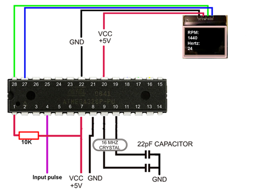
The ATmega328p chip receives the input signal on pin 2 (physical pin 4). Pin 2 is one of the
two
interrupt pins. In the Arduino sketch an interrupt routine is called on the rising edge (when pin 2
goes from low to high). A counter is incremented. After 3 seconds the interrupt routine is halted
(detached) and the counter is used for the calculation of hertz and rpm. The result is written to the
oled 128x64 display and the interrupt routine is restarted (attached).
A variable used in an interrupt routine must be declared as volatile and do not do any calculations
with this variable. It messes up the routine. Just copy it into another variable.
>>> Arduino code <<<
Brushless motor with IR sensor
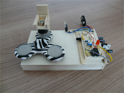 The fidget spinner has a magnet in each of its 3 arms. The
electromagnet is made out of a plastic
spindle from a sewing machine and the wire used to wind onto the spindle is coated copper with an
enamel coating that must be removed from the ends to make an electrical connection. The wire is 34 AWG
and a drilling machine with variable speed is used to wind the coil.
Turning the electromagnet on and off is done by an IR sensor circuit, the same circuit as for the
tachometer.
Rotation direction depends on the positioning of the IR-pair as demonstrated in the video. To power the coil 9
volt is applied, but the IR-sensor circuit has a maximum of 5 volt. An LM7805 voltage regulator
brings the 9 volt down to 5.
  There are 4 bypass capacitors, 2 on the
input and 2 on the output. Their function is to smoothen out any spikes in the voltage.
Click
here
to see the video.
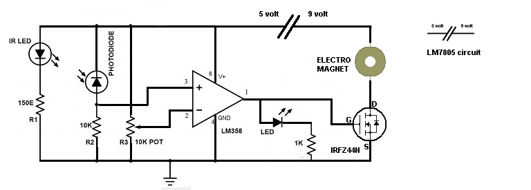 Electromagnet IR sensor
Brushless motor with reed switch
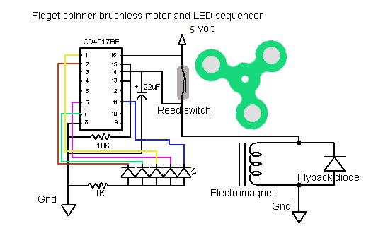
 The electromagnet is turned on when a magnet is near the reed switch. The contacts inside the switch close the circuit.
The reed switch is also used as a clock signal for the decade counter 4017. Only 5 of the 10 possible LEDs are used. The 22 uF capacitor
is necessary to smoothen the voltage spikes or the 4017 IC goes bonkers. The rotation speed is about 40 Hz using a strobe light app.
Click
here
to see the video.
Simon says
"Simon says" is a memory game with 4 buttons, 4 LEDs and a speaker. Follow the pattern of lights and sounds and repeat the same combination. It starts with one light (+sound), then 2 and so on, until it reaches 10 and the game is over. As a player you have to memorize the series of lights and sounds and than reproduce it by pushing the buttons in the same order. The challenge was to write the Arduino sketch for this game. Click here to see the video.
>>> Arduino code <<<


